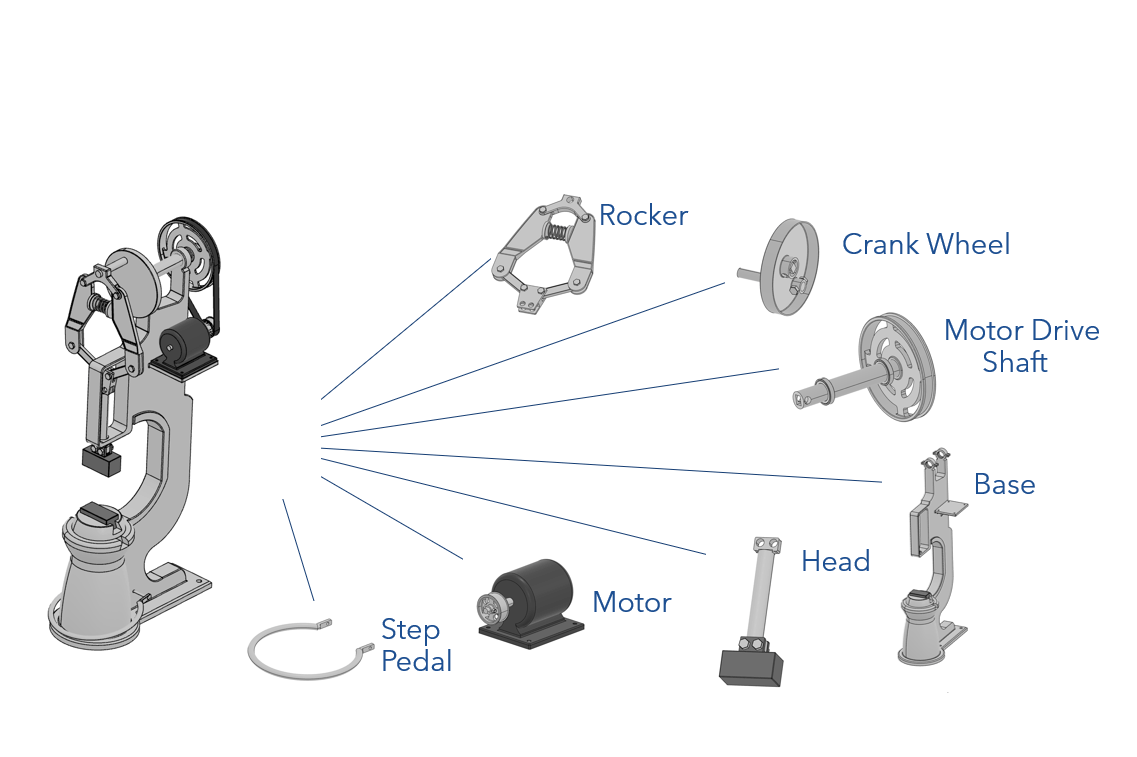
A power hammer consists of 7 distinct sub assemblies:
A Base - Houses all the components
A Motor - Drives the mechanical assembly
A Ram - Oscillates up and down and deforms the metal
A Drive Shaft - Spins according to the motor
A Crank Wheel - Turns rotational into translational motion
A Rocker - Transfers motion from the crank to the ram
Step Pedal - Controls the speed of the motor
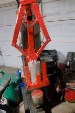
Based upon historical models, the dimensions for the base was approximated and the remaining parts were created to be proportional to the base. For the initial design, geometries were typically made bulkier to ensure a viable model.
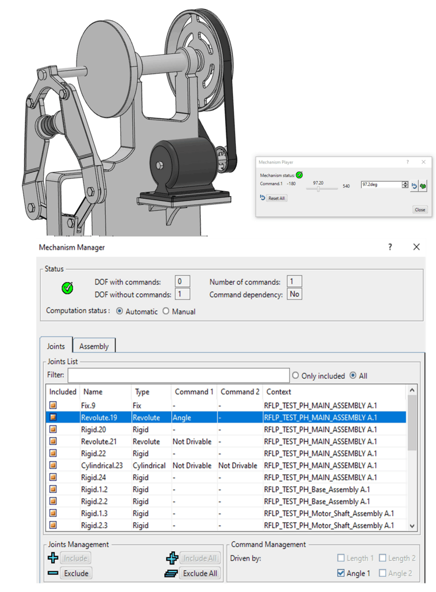
Controlled rotational angular mechanisms were created for the main drive, the motor, and the step bar within the main assembly with only a single degree of freedom (DOF) without any commands.
This was achieved through carefully selecting the required engineering connections to include in the assembly and resepective mechanisms.
It's important that the mechanisms were created this way to ensure an accurate simulation.
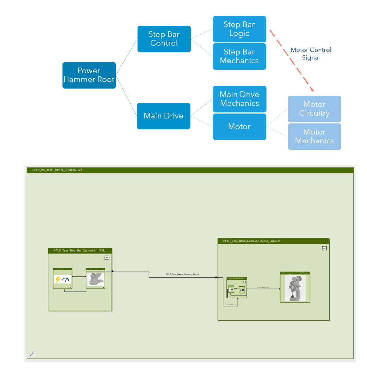
FLE Architecture
The FLE logical architecture frame work has logical components that are joined using logical connections to exchange data. Each component is nested within a parent component and contains CATIA models and Dymola behaviors.
Main Drive
The Main Drive Component contains the Dymola models for the main assembly and motor kinematics as well as the motor circuitry. The motor circuitry actuates the mechanical components in the main drive.
Step Bar Control
The Step Bar Control component actuates the mechanical step bar in the assembly as well as sends a control signal to the motor circuitry in the Main Drive component based off of a pre-defined routine.
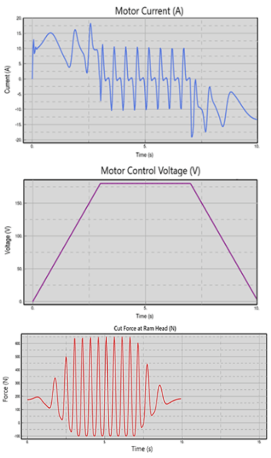
The resulting model produced over 600N of force (~100lbs. when accounting for gravity) which would be sufficient for small scale industrial forging.
For a 2 HP motor the resulting current draw waveform was observed which exceeded the nominally rated current during start up. As such it was determined that an inrush current limiter circuit or a stronger motor would be required.
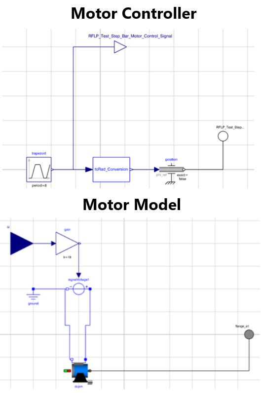
Motor Controller
A trapezoidal signal is sent to both the motor and the step bar mechanics. This signal represents the angular value of the step bar and the intensity of the motor.
Motor Electronics
The trapezoidal signal from the motor controller is amplified by a gain and acts as the voltage for a DC permanent magnet motor (DCPM) which transmits torque to the main mechanical assembly. This motor component is connected to a geared component which models the belted connection between the motor and the main drive.
1. Cut Pieces
1" steel square tubing and 2" steel sqaure tubing was used for the rocker and main assembly. These peices were cut using an angle grinder and from assembly geometries.
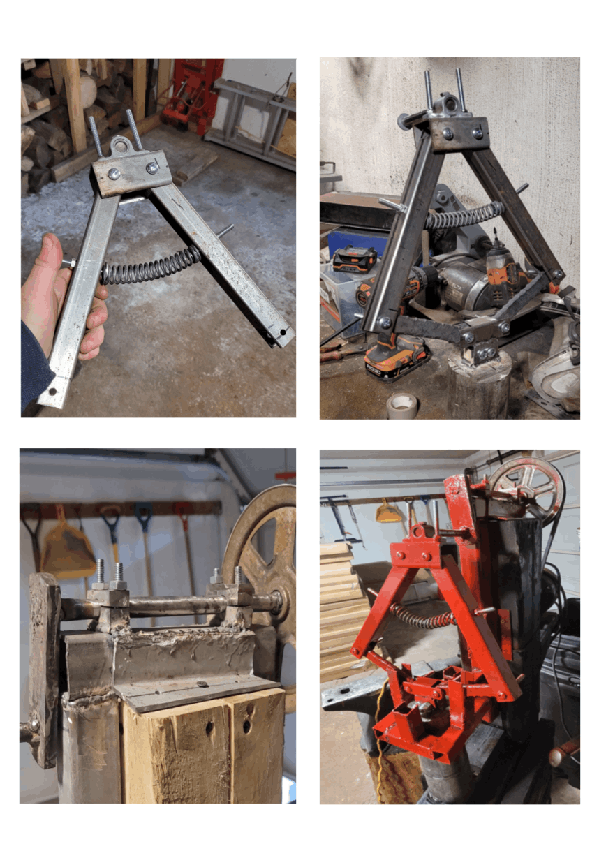
2. Assemble Rocker
The rocker was create primarily using bolted connections to allow the arms to pivot and to fix the spring between the arms and a pillow block on top.
3. Create Base Fixture
The base was created from screwing together wooden blocks in 1' sections. This created a strong cohesive base and was weighty enough to prevent the assembly from rocking. An 'L' beam was created by MIG welding square tubing together and was mounted to the wooden base.
4. Mount Ram
A 15lb. steel cylinder was cut and a block was welded to it to serve as the ram head. This allowed for a bolted connection between the rocker and the ram. The remaining half of the steel cylinder was mounted to the base for the lower dye.
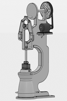
5. Create Crank, Tolerance Bearings & Mount
Tolerance bearings were created that held the drive shaft in place and the seperable design allowed for the main shaft to be removed/dissasembled from the base for maintenance. The bearings were lined with grease to increase lubrication.
6. Mount Motor & Control
A 1/2 HP motor was mounted at the back of the assembly to keep it balanced and a belt connects the motor to the main drive wheel. A 15A motor speed controller was also purchased to control the speed of the motor and was mounted to the side of the base.